Continuous Insulation Solutions for Cold-Formed Steel Thermal Bridging
By Carlos Ferreira · April 7, 2026
Continuous Insulation Solutions for Cold-Formed Steel Thermal Bridging
A Technical Guide to Code-Compliant Wall Assemblies in Climate Zone 5A
AAC Steel Engineering Division | April 2026
AAC Steel | Franklin, MA
Introduction: The Thermal Bridging Problem in CFS Construction
Cold-formed steel (CFS) framing delivers exceptional structural performance in multifamily and mid-rise construction, but its high thermal conductivity creates a well-documented challenge: thermal bridging. Steel studs conduct heat approximately 400 times faster than wood, meaning a CFS wall assembly rated at R-20 based on cavity insulation alone can degrade to an effective whole-wall R-value of approximately R-5 once thermal bridging is accounted for. That 75% performance loss is not a theoretical concern; it is a code compliance failure waiting to happen.
The solution is continuous insulation (ci), an uninterrupted thermal barrier applied to the exterior of the CFS framing that breaks the conductive path through the steel studs. ASHRAE 90.1-2019 and the 2021 International Energy Conservation Code (IECC) both mandate continuous insulation for steel-framed assemblies in Climate Zone 5A, which includes all of Massachusetts. The Massachusetts Stretch Energy Code, adopted as the baseline in 232 of 351 municipalities, goes further: it is the first energy code in the United States to explicitly address thermal bridging with prescriptive ci requirements for steel framing.
AAC Steel provides thermal analysis services alongside CFS fabrication to help design teams select wall assemblies that satisfy code requirements while maintaining constructability. This article examines the primary continuous insulation materials, compares their performance characteristics, and outlines practical wall assembly configurations for Zone 5A compliance.
Understanding Thermal Bridging in CFS Assemblies
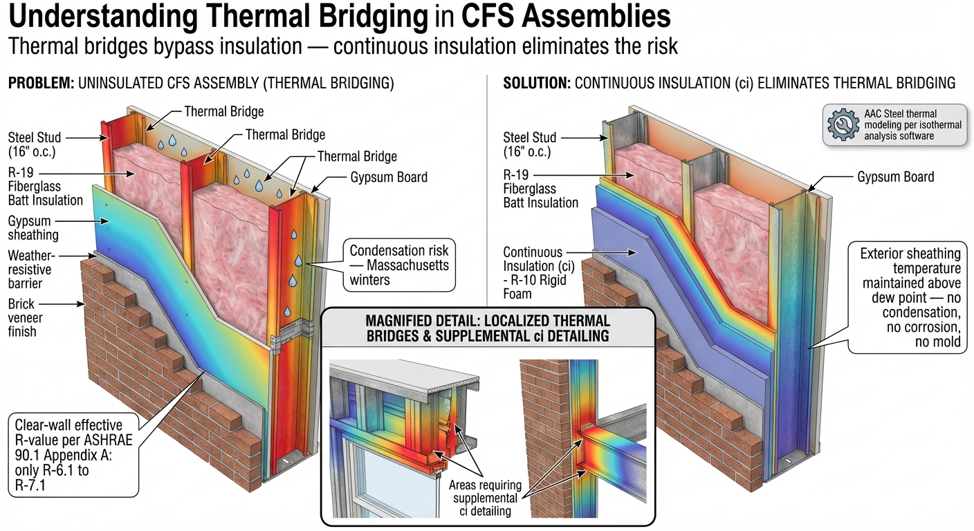
Thermal bridging occurs wherever a highly conductive material spans the building envelope, creating a preferential path for heat flow that bypasses the surrounding insulation. In CFS construction, every stud, track, header, and clip acts as a thermal bridge. The effect is cumulative: a typical 6-inch CFS wall framed at 16 inches on center with R-19 fiberglass batts achieves a clear-wall R-value of only R-6.1 to R-7.1 when thermal bridging is calculated per ASHRAE 90.1 Appendix A.
The consequences extend beyond energy loss. Thermal bridges drive interior surface temperatures below the dew point, promoting condensation within the wall cavity. In Massachusetts winters, this condensation cycle accelerates corrosion of CFS members and can support mold growth on interior finishes. Continuous insulation eliminates these risks by maintaining the exterior sheathing temperature above the dew point across the entire wall plane.
AAC Steel engineers routinely perform thermal modeling on proposed wall assemblies using isothermal analysis software. These models quantify the effective R-value of each assembly and identify localized thermal bridges at structural connections, window headers, and floor-line transitions, areas where supplemental ci detailing may be required.
Continuous Insulation Materials: Performance Comparison
Three material families dominate the continuous insulation market for CFS construction: mineral wool boards, extruded polystyrene (XPS), and polyisocyanurate (polyiso). Each offers distinct advantages depending on project fire rating requirements, moisture management strategy, and budget constraints.
Mineral wool (stone wool) provides R-4.2 per inch of thickness and is classified as non-combustible per ASTM E136. It is inherently moisture permeable, allowing vapor to diffuse through the insulation layer without trapping moisture against the sheathing. For Type IIB and Type IIIA construction where non-combustible exterior insulation simplifies fire-resistance assemblies, mineral wool is the default choice. AAC Steel specifies mineral wool ci on the majority of its multifamily projects in Massachusetts for this reason.
Rigid XPS boards deliver R-5.0 per inch and offer high compressive strength, making them suitable for below-grade applications and assemblies requiring mechanical attachment through the insulation. However, XPS is combustible and requires an ignition barrier or thermal barrier depending on the application, which adds cost and complexity to fire-rated assemblies.
Polyisocyanurate (polyiso) offers the highest R-value per inch at R-6.5, enabling thinner wall assemblies for a given thermal target. Polyiso performs well in above-grade wall applications but exhibits R-value derating at low temperatures, a consideration in Zone 5A winter conditions where exterior insulation surface temperatures may drop below 40 degrees Fahrenheit. Designers should use the LTTR (Long-Term Thermal Resistance) values published by manufacturers when specifying polyiso for Massachusetts projects.
Insulation Material Comparison
| Property | Mineral Wool | XPS (Extruded Polystyrene) | Polyiso (Polyisocyanurate) |
|---|---|---|---|
| R-Value per Inch | R-4.2 | R-5.0 | R-6.5 (LTTR) |
| Combustibility | Non-combustible (ASTM E136) | Combustible (requires barrier) | Combustible (requires barrier) |
| Moisture Permeability | High (vapor open) | Low (Class I vapor retarder) | Low to moderate |
| Compressive Strength | Moderate (3-5 psi) | High (15-25 psi) | Moderate (16-25 psi) |
| Cold-Weather Performance | Stable | Stable | R-value derates below 40F |
| Typical Cost (per sq ft, 2") | $1.80-$2.40 | $1.20-$1.80 | $1.40-$2.00 |
| Fire-Rated Assembly Use | Ideal (non-combustible) | Requires ignition barrier | Requires thermal barrier |
| Best Application | Multifamily, Type IIB/IIIA | Below-grade, high-load | Max R-value in thin profile |
Zone 5A Code Requirements for Continuous Insulation
Massachusetts falls within IECC Climate Zone 5A, which imposes specific continuous insulation requirements for steel-framed assemblies. Under the 2021 IECC prescriptive path, steel-framed walls in Zone 5A require a minimum of R-13 cavity insulation plus R-7.5 continuous insulation, or R-20 cavity plus R-3.8 ci. The ASHRAE 90.1-2019 prescriptive requirements align closely, mandating R-13 + R-7.5ci for steel-framed walls.
The Massachusetts Stretch Energy Code raises the bar. As the first US code to explicitly address thermal bridging, it requires designers to demonstrate effective thermal performance of the assembly rather than relying on nominal insulation values. This means thermal bridging must be accounted for in energy modeling, and assemblies that rely solely on cavity insulation will not pass compliance review.
AAC Steel's thermal analysis service calculates the whole-wall effective R-value for each proposed assembly, accounting for the thermal bridging effects of steel studs, tracks, clips, and structural connections. This analysis provides the documentation required for Stretch Code compliance and supports the COMcheck or energy model submissions required by code officials.
Representative Wall Assemblies for Zone 5A
| Assembly Component | Assembly A (Prescriptive Min) | Assembly B (High Performance) | Assembly C (Passive House) |
|---|---|---|---|
| CFS Studs | 6" at 16" o.c., 20 ga | 6" at 16" o.c., 18 ga | 6" at 16" o.c., 18 ga |
| Cavity Insulation | R-19 mineral fiber batt | R-19 mineral fiber batt | R-21 spray-applied |
| Exterior Sheathing | 5/8" dens-glass gypsum | 5/8" dens-glass gypsum | 5/8" dens-glass gypsum |
| Continuous Insulation | 1" mineral wool (R-4.2) | 2" mineral wool (R-8.4) | 3" mineral wool (R-12.6) |
| Drainage Cavity | None (face-sealed) | 3/4" rainscreen | 3/4" rainscreen |
| Effective Whole-Wall R | R-14 to R-16 | R-25 to R-27 | R-30 to R-33 |
| Code Compliance | IECC Zone 5A minimum | Exceeds Stretch Code | Passive House eligible |
| Estimated Wall Cost/SF | $18-$22 | $24-$28 | $30-$36 |
Hybrid Wall Assemblies: Achieving R-25+ Whole-Wall Performance
The highest-performing CFS wall assemblies combine cavity insulation with exterior continuous insulation in a hybrid configuration. A typical high-performance assembly consists of 6-inch CFS studs at 16 inches on center with R-19 mineral fiber cavity insulation, exterior gypsum sheathing, 2 inches of mineral wool ci (R-8.4), a drainage cavity created by vertical hat channels, and a rainscreen cladding system.
This assembly achieves a whole-wall effective R-value of approximately R-25 to R-27, depending on stud gauge and spacing. The mineral wool ci layer breaks the thermal bridge at every stud location, while the drained and ventilated rainscreen cavity manages bulk water and allows outward drying of the wall assembly.
For projects targeting even higher performance, such as Passive House certification or net-zero energy goals, AAC Steel has detailed assemblies achieving effective R-values above R-30 using 3-inch mineral wool ci (R-12.6) combined with R-21 cavity insulation in 6-inch studs. These assemblies require careful structural detailing at cladding attachment points, and AAC Steel provides engineering support for the cladding connection design through the ci layer.
The embodied carbon benefits of CFS with continuous insulation are significant. Adaptive reuse and renovation projects using CFS framing with exterior ci achieve 50 to 82 percent less embodied carbon compared to new conventional construction, depending on the extent of existing structure retained. AAC Steel works with design teams to quantify these benefits for projects pursuing LEED, Envision, or other sustainability certifications.
Installation Best Practices for CFS with Continuous Insulation
Proper installation of continuous insulation on CFS framing requires attention to several critical details that distinguish steel-framed assemblies from wood construction.
First, insulation joints must be staggered and sealed. Unlike wood framing where minor gaps are partially mitigated by the lower conductivity of the substrate, any gap in ci over a steel stud creates a concentrated thermal bridge. AAC Steel recommends taping all ci board joints with manufacturer-approved foil or acrylic tape.
Second, mechanical attachments through the ci layer must be thermally isolated. Cladding support clips, shelf angles, and through-wall fasteners that penetrate the ci and contact the CFS framing reintroduce thermal bridges. Thermally broken clips, such as fiberglass or stainless steel standoffs, should be specified at cladding attachment points. AAC Steel can provide shop drawings showing thermally broken cladding connections coordinated with the CFS framing layout.
Third, transitions at floor lines, window openings, and parapet conditions require continuous ci coverage. These are the locations where thermal bridging is most severe because structural members are concentrated. AAC Steel's fabrication drawings identify these conditions and provide ci coverage details as part of the standard deliverable package.
Fourth, fire barrier and draft stop requirements per IBC Section 718 must be coordinated with the ci installation. In combustible ci applications (XPS, polyiso), fire barriers at floor lines and draft stops at specified intervals are mandatory. Non-combustible mineral wool ci simplifies this coordination significantly.
Frequently Asked Questions
- What is the minimum continuous insulation thickness required for CFS walls in Massachusetts?
- Under the 2021 IECC prescriptive path for Zone 5A, steel-framed walls require R-7.5 ci when paired with R-13 cavity insulation, or R-3.8 ci when paired with R-20 cavity insulation. The MA Stretch Code may require additional ci thickness depending on the thermal bridging analysis of the specific assembly. AAC Steel's thermal analysis service determines the exact ci thickness needed for code compliance on each project.
- Can I use cavity insulation alone in a CFS wall and meet code?
- No. No amount of cavity insulation alone can compensate for the thermal bridging effect of CFS studs in Zone 5A. Both ASHRAE 90.1 and the IECC require continuous insulation as a mandatory component of steel-framed wall assemblies. Attempting to meet energy code requirements with cavity-only insulation in a CFS wall will result in compliance failures.
- Which continuous insulation material is best for Type IIB construction?
- Mineral wool is the preferred ci material for Type IIB (non-combustible) construction because it is classified non-combustible per ASTM E136. Using combustible ci materials (XPS, polyiso) in Type IIB construction requires NFPA 285 fire testing of the specific wall assembly, which adds cost and limits design flexibility. AAC Steel recommends mineral wool ci for all Type IIB projects.
- How does AAC Steel support continuous insulation design?
- AAC Steel provides three levels of ci support: (1) thermal analysis calculating the effective whole-wall R-value of proposed assemblies, (2) fabrication drawings that identify ci coverage requirements at structural transitions, and (3) cladding connection engineering through the ci layer. Contact AAC Steel at aacsteel.com to discuss your project requirements.
- Does continuous insulation affect the structural design of the CFS framing?
- The ci layer itself does not carry structural loads, but the cladding attachment method through the ci layer directly affects the CFS framing design. Thicker ci requires longer fasteners or outrigger clips, which change the load path for wind and seismic cladding loads. AAC Steel coordinates ci thickness with cladding attachment engineering as part of every project.
- What is the cost impact of adding continuous insulation to a CFS wall?
- Continuous insulation typically adds $2.50 to $5.00 per square foot of wall area for material and installation, depending on ci type and thickness. However, ci often allows downsizing of HVAC equipment, reduces long-term energy costs, and is required for code compliance. The net project cost impact is typically neutral to positive when lifecycle costs are considered. AAC Steel can provide assembly cost comparisons for your specific project.